

The above image borders were extended by 2000 pixels (in width) to each side using the “Overscan” script
Video Captions available (CC)
Video Captions available (CC)
Video Captions available (CC)
Video Captions available (CC)
Video Captions available (CC)


There will be times when
clients will ask users to revisit old projects, with the purpose to redesign
and/or re-render an existing camera view.
When re-rendering an existing camera view, the client may also require users to include more of the 3D scene in the same shot; preferably without affecting the perspective (e.g. almost like extending the borders of a PSD canvas).
In real technical terms such requirement is impossible to achieve, as it defies the physics of any real camera.
Having said that, that’s often what’s required from most users: To do the impossible.
Until recently, many well-known studios (including myself) would “achieve” the above mentioned request by first decreasing the original FOV of the camera in order to cover new areas of the 3D scene; followed by increasing the original render output size (pixels) many times over in order to compensate for the reduced FOV values.
The above described process was clearly a “workaround” to meet the client’s request…until I was introduced to an ingenious script called “Overscan”.
The script was created by Martin (martin@breidt.net) at http://www.breidt.net/scripts/index.html#overscan , to solve the tedious “workaround” described earlier.

The script only works with standard 3ds Max cameras.
It’s also recommended to save the current 3D scene under a
different name prior to using this script, as a precautionary measure.
To implement the script, users are simply required to do the
following:
1- Download the
script from the above mentioned link.
2-Open the 3Ds
Max file, followed by dragging and dropping the script from the folder,
directly onto your camera viewport.
3-The script's
dialog box should pop up immediately, with the original output image size
dimensions.

The “New Width” and the “New Height” functions allow users to input new dimension values.
The “rel” button locks the original proportion dimensions,
so that new added values will always be in proportion to the “Old size”
dimensions.
The “Apply Overcan” button updates the camera with the new
dimensions entered in the “New Width” and the “New Height” name field. If the
“Copy camera” function is enabled, a new camera will be created and named
accordingly.
The “Update” button updates the “Old size” dimensions with
the new ones entered.
In the figure below, the height of the image output was
changed from the original 3000 pixels, to 5000 pixels, without affecting the
perspective.
A new camera was also created automatically, by simply
enabling the “Copy camera” function and clicking on the “Apply Overscan”
button.


Since the original script was created for standard 3ds Max cameras
only; users with a Vray physical camera in the scene, should do the following:
1- First open your VRay Max scene and go to the VRay camera
viewport.
2- Press “P” from your keyboard to turn the current Vray
camera viewport into a “Perspective” one.
3-Next, press “Ctrl+C” from your keyboard to automatically
create a 3ds Max standard camera.
4- A new camera should be created automatically. Next, follow
the steps covered earlier to apply the “Overscan” script.
5- Once satisfied with your new camera settings and the output
dimensions, run a script to convert the 3ds Max standard camera into a Vray
physical camera.
The script I often use is called “MaxCam_To_PhysCam_1.4_proc”. And can be downloaded from the
following location:
http://www.scriptspot.com/3ds-max/scripts/leles-vray-tools
http://www.scriptspot.com/3ds-max/scripts/leles-vray-tools
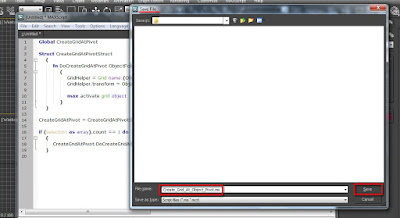
To run the script, simply do the following:
1- After downloading and unzipping the file, simply click on
the “MaxScript” main toolbar.
2-On its dropdown list, choose to “Run Script”.

3- The “Choose Editor File” dialog should appear.
4- Locate and open the “MaxCam_To_PhysCam_1.4_proc” from the list.

5- The “Physcam Converter V1.4” dialog should appear. Select the relevant camera(s) from the scene, and click on the “Convert Camera(s)” button.
A new Vray physical camera should be created, named
accordingly and selected automatically.
To view the newly created camera, simply press “C” on the
keyboard. Alternatively, simply right click on the camera name situated on the
top left corner of the camera viewport, and choose the relevant camera.

6- Finally, copy the Vray exposure parameters from the original camera settings onto the newly created one.
Overriding useless Backburner errors
Most users would agree that, more often than not, the
Backburner can be “spot on” when pinpointing valuable errors in the render(s).
However, there are times when it can also be an utter nuisance and ultimately
prevent users from meeting their looming deadlines.
Very recently, I was involved in a project that was an
absolute joy from the word “go”…until my beloved Backburner began reporting
useless errors.
Some of the messages read the following: “3dsmax adapter
error: AutodeskMaxDesign 14.12 reported error:JPEG- Memory Error”.
And also: “3dsmax adapter error: AutodeskMaxDesign 14.12
reported error: “…jpeg—Failed to allocate filter tables for this bitmap…”.
The frustration was that, all bitmaps bigger than 1500
pixels were proxied in the scene. Furthermore, the Backburner would render the
entire frame with its elements perfectly; followed by re-rendering it over and
over again, due to the above mentioned errors.

After few Google searches on the subject, I quickly realized that this was clearly a problem that had many professionals pulling their hair out (if any left) so far.
I nearly threw in the towel on this one... until - Jordan Barlow (jordan_barlow@hotmail.com)-
came up with an ingenious way to override this niggling “bug”.
Please do the following to emulate his approach:
1- Open the “Backburner
Manager” dialog first, followed by clicking on the “Edit” toolbar, and choosing
the “General settings” option from the dropdown list.
2- The
“Backburner Manager General properties” dialog should appear promptly. In the “General” group, enable the “Use Task
Error Limit Max Errors Per Task” function, and set it to 1.
This action will limit the amount of times (1) the
Backburner will continue to mistakenly try to solve (re-rendering) an error
that doesn’t exist, or an error that’s Not affecting any aspect of the render(s).


Create
and snap a grid helper perfectly to any given geometry and/or spline, in any angle
While this subject was covered to some extent in my latestbook, I have never addressed this specific issue before.
To address the above mentioned issue, users should simply
resort to a script called “Create_Grid_At_Object_Pivot”.
The name of its creator is paul.hormis@hypercent.com (assuming).
Furthermore, to create the above mentioned script one has to do the following:
1-In 3ds Max, click on the MaxScript button from the main toolbar, and choose the New Script option.
A new Script dialog should open.

A new Script dialog should open.


2- In this blog, select and copy (Ctrl+c) the following script text below:
Global CreateGridAtPivot
Struct CreateGridAtPivotStruct
(
fn DoCreateGridAtPivot ObjectForGrid =
(
GridHelper = Grid name:(ObjectForGrid.name + "Grid") isselected:on
GridHelper.transform = ObjectForGrid.transform
max activate grid object
)
)
CreateGridAtPivot = CreateGridAtPivotStruct()
if (selection as array).count == 1 do
(
CreateGridAtPivot.DoCreateGridAtPivot $
)

3-After copying(Ctrl+c) the above mentioned script from this blog; go back to the new Maxscript dialog in 3ds Max, and paste it (Ctrl+v) onto it:

4- Next, save the script by clicking on the "File" button and choosing the "Save As" option.

5-The "Save As" dialog should be prompted. Save it as an *.ms file type; under the name of, Create_Grid_At_Object_Pivot
To run the previously saved “Create_Grid_At_Object_Pivot.ms” script, simply do the following:

5-The "Save As" dialog should be prompted. Save it as an *.ms file type; under the name of, Create_Grid_At_Object_Pivot

To run the previously saved “Create_Grid_At_Object_Pivot.ms” script, simply do the following:
1-Open 3Ds max and create a shape or geometry. Also,
rotate/position it in an awkward angle.

2- Next, while the
shape/geometry is still selected, click on the “MaxScript” button from the main toolbar, and
choose to “Run Script” from its drop down list.

3- The “Choose Editor File” dialog should appear. Locate and "Open" the previously saved script under the name of “Create_Grid_At_Object_Pivot.ms” .

4- A grid should automatically appear in the correct angle/position, and enabled by default. To test its accuracy, simply begin creating anything in the viewport.


Using the mental ray connection to access a displacement shader
In the past, a number of people had asked me if there was a
way to override the default Arch & design displacement shader with a better
one, in order to achieve better results.
To access a new displacement shader from the Arch &
Design, simply do the following:
1- Open the “mental ray Connection” rollout and scroll down
to the “Extended Shaders rollout” group.
2-Unlock the padlock button by clicking on it, and click on
its toggle to access the “Material/Map Browser” dialog.
3- I personally choose the “Height Map Displacement” shader from the list, as it’s faster to
render. However, feel free to choose another one, if desired.
4- The “Height Map Displacement” shader parameters are simple and self-explanatory.


Vray subpixel mapping function
Again, while this subject was covered in my latest book, I
thought it would be nice to share it with those that don’t have the book (yet).
Ever wondered how to correct the artifact depicted in the render below?
Ever wondered how to correct the artifact depicted in the render below?

The above described artifact can be instantly corrected by
simply enabling the “Sub-pixel mapping” function.


V-Ray:: Irradiance
map Interp. Samples
When using the irradiance map, at times the default “Inter. samples” value of 20 may work for a 1920x1080 pixels render. However, when rendering a 5000x2813 pixels image, it may yield artifacts such as the one demonstrated below. 

Note: Such artifacts are more noticeable on white or bright surfaces.
To rectify such artifacts, users should simply increase the default “Inter. samples” value to 70 or as high as 90, if necessary. There are extreme cases when one might need to enter higher values.


Note: It is suggested that, by increasing the “Inter.
samples” values as mentioned earlier,one may cause the scene to lose depth.
If such happens (debatable), one can still add more depth by
using key VRay render elements such as VrayRawTotalLighting; VrayRawLighting; VrayTotalLighting;
Vrayshadows; etc).
I hope you have found the tips and tricks useful!
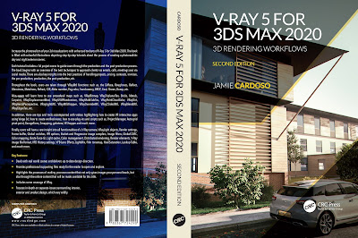
Finally, I have just published a New Book with Taylor & Francis/CRC Press, entitled,
V-Ray 5 for 3ds Max 2020: 3D Rendering Workflows
Click on the image below to find out more about my new book.
Checkout below my other Courses with High Resolution Videos, 3d Project files and Textures included.
 |
| Course 1: Exterior Daylight with V-Ray + 3ds Max + Photoshop |
Course 2: Exterior Night with V-Ray + 3ds Max + Photoshop |
| Course 4: Interior Daylight with V-Ray + 3ds Max + Photoshop |
 |
| Course 5: Interior Night with V-Ray + 3ds Max + Photoshop |
 | |||||
Course 6: Studio Lights with V-Ray + 3ds Max + Photoshop
|


Also, please Join my Patreon page or Gumroad page to download Courses; Project files; Watch more Videos and receive Technical Support. Finally, check my New channels below:


New Book: 3D Photorealistic Rendering: Interiors & Exteriors with V-Ray and 3ds Max
Post-production techniques
Photorealistic Rendering
Creating Customised IES lights
Realistic materials
Creating a velvet/suede material
Great post as always Jamie!
ReplyDeleteHi ColonelClaw,
ReplyDeleteThank you very much!
Ta
Meu amigo, sem comentários! exelente material!! muito obrigado! queria saber falar inglês para obter seu livro.
ReplyDeleteJuarez and the engineering design: Thank you very much for your kind comments here!
ReplyDeleteIf you happen to have suggestions about new tutorials and /or tips, please email me on:
ReplyDeletejamiecardo@hotmail.com
Ta