

To access and Download this full course, please click HERE
Tips & tricks for architectural Visualisation & Verified Views for Planning Applications: Part 2
This part 2 series will focus mainly on proprietary rendering tools such as batch camera render; and on a fantastic tool/script for Verified Views Methodology/Planning
Verified View/s methodology or Accurate Visual Representation (AVR):: Is an accurate Photomontage of a proposed design/building, using the Guidelines for Landscape and Visual Impact Assessment (GLVIA3).
-------------------------------------------------------------------------------------------------------------
Key Aspects of Verified Views
"Verified Views" are distinct from standard artistic photomontages due to a rigorous, data-driven process:
- Survey Data: The process involves a professional surveyor recording the exact camera location, height, lens details, GPS data, and specific key points in the physical environment.
- Accurate 3D Model Alignment: This survey data is used to accurately align a detailed 3D model of the proposed development within the real-world photograph, ensuring correct scale, perspective, and spatial relationships.
- Council Compliance: This methodology ensures the final image is a robust and defensible representation of the proposed development, which is often a key requirement for local authorities when assessing visual impact.
Companies work with architects, developers, and planning consultants to produce the necessary documentation to aid in securing planning approvals.
-----------------------------------------------------------------------------------------------------------------
Photomontage in 3d Visualization: Is the process of incorporating a 3d object/design/building into a 2d image/photo, while matching the camera angle/settings, position and the overall lighting depicted in the 2d photo.
This laborious process often requires the usage of a 2d and a 3d application.
For more information about this entire process, please check the PDF link below I have put together for gobotree.com
3d Photomontage Process: https://drive.google.com/file/d/1iRoJbfqh9e3pSVm7Fx4aipuJQk6oKRbl/view?usp=sharing

To create an accurate Photomontage/Verified View, the 3d Visualizer/specialist needs a: 3d context model to plot/plan and create the shots; a photo of the location in question; the survey data; camera information; a 2d and a 3d application to create the Final Verified View/s .
Some of the articles, The above Video, and tutorials depicted in this blog will take you through the entire process.
Planning Applications: These can be used to find out whether a proposed development is likely to be approved by the planning authority, before substantial costs are incurred developing a detailed design.
Planning Permissions: Is the legal process of determining whether proposed developments should be permitted. Responsibility for planning lies with local planning authorities (usually the planning department of the district or borough council). The legislation, policy and guidance that underpins planning in England can be found on the government's National Planning Practice Guidance
Play the above Video in Full HD and with Subtitles (CC)


The above video tutorial takes users through the step-by-step process of creating an entire new Verified View Accurately, with one click of a button, using this Amazing New 3ds Max script.
Within less than one second, this amazing new script Automatically and Simultaneously creates accurate survey points in the scene, based on the surveyor’s information.
With one simple click, this new 3ds max script, will save users countless hours of work per verified view, or days, if working on multiple camera views.
Creating verified views for planning applications has never been easier, quicker and more accurate.
Key 3ds Max Script features instantly/automatically created simultaneously with one click:
1-Accurately creates and places the survey point coordinates in the 3ds Max scene instantly using/sourcing the data from the surveyor and the photographer’s data spreadsheet.
2- Accurately creates and places the physical camera in the 3ds Max scene instantly using/sourcing the data from the surveyor and the photographer’s data spreadsheet.
3- Accurately creates and places the daylight system in the 3ds Max scene instantly using/sourcing the data from the surveyor and the photographer’s data spreadsheet.
4- Accurately creates, names and places the physical camera in the 3ds Max scene instantly using/sourcing the data from the surveyor and the photographer’s data spreadsheet.
5- Accurately sets up the render Output Size and padlocks it based on the background image size instantly using/sourcing the data from the surveyor and the photographer’s data spreadsheet.
6-
7-And much more…
*Latest Updates for this 3ds Max Script :
The script now looks at a folder named "images" to directly source the camera viewport background image from. The settings.csv file NO LONGER has the " viewport_background_image" column to enter the directory and file name.
So, users can simply place/replace and rename any viewport background image file in the "images" folder. The folders named "images" and "settings" CANNOT BE RENAMED though.
The Full 3ds Max script comes with the following:
1-The 3ds Max script

2-The "settings" spreadsheet file with the scene's settings data (*.csv)

3-The surveyor's "Survey_Data_Coordinates" spreadsheet file (*.csv)

4-The surveyor's background image for view 6

5-The folders/directory already setup


Key Notes:
The 3ds Max script requires two separate spreadsheet files in order to instantly generate the entire scene with accurate survey data points, physical camera, background image, daylight system, etc:
1-One spreadsheet file with survey coordinates
2-Another spreadsheet file with the scene settings.
The spreadsheet file formats need to be *.csv, otherwise the 3ds Max script will generate errors when running.
The folders and file names cannot have spaces between the words. Use underscores instead. Otherwise, the 3ds Max script will generate errors when running.
The surveyor’s coordinate spreadsheet file with survey coordinates needs to be in the same folder as the 3ds Max script.
The spreadsheet file named settings.csv needs to be in separate folder named “settings”. The folder names CANNOT be renamed.
The csv file names can be renamed according to their project names (e.g. V6_scene_settings.csv) .
There can only be one main spreadsheet csv file in each of the folders the 3ds max script will be referencing from.
To download the full 3ds Max script with files, please contact me directly, or visit my Gumroad page HERE:
Prior to creating and signing off each camera view with the architects/developers, you need to do the following first:
Get a map/drawing depicting the proposed Distant Views from the architects/developers

Find a 3d context model covering the above mentioned area/s. Zmapping provides excellent 3d context models for verified views.
To extract the 3d context model, do the following:
a)-Go to Zmapping website and click "Get a quote"

b)- In the "Find Location" section, type in the location and click on "Add Polygon" button

c)- Following that, click on "choose a type of polygon" and pick one from the list

d)- Once the type of polygon is chosen, click on "Click here to start plotting"

e)- Click anywhere on the satellite map
A square box should appear
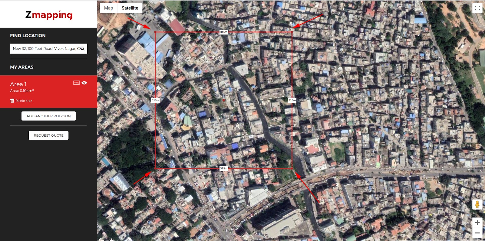
f)-Hover over one of the polygon points until you see the finger mouse symbol

g)-Begin moving each of the points (if/when necessary) until you cover the desired area

h)- Once satisfied with your area, click on the "Request quote" button, fill in the details and "Get a quote".

You should receive the context model shortly after.
Once you receive the 3d context model from Zmapping, set up your camera views in 3ds max, to match the above mentioned proposed views,
The proposed new 3d building should also be inserted.
Send out the CG (computer Generated) "chalk renders" of the proposed views to the architects/developers, for revision/approval .
Once the camera views have been approved/signed off by the architects/developers, organize a Surveyor and a good Photographer to go on site to survey and photograph the agreed/signed off views.
Prior to sending the Photographer and the Surveyor to the site, you need to do the following first:
a)- Mark up the position/location, and the number of survey points you want on each of the agreed/signed off camera views ( mark up/circle around at least 10 survey points on each of the CG "chalk renders") .
b)- Ensure the Photographer chooses the ideal day/time to take stunning photos
Surveyor's Equipment Required
• Global Positioning System (GPS)
• Total Station (with good reflectorless EDM range)
• Precise Level
Field Survey Methodology
• It should be noted that some locations will often contain coincidental reference points and hence the work should be carefully analysed to prevent excessive back-tracking
• Camera Locations - To establish the position of a viewpoint, the surveyor must set up a GPS on it and record enough points to ensure a high level of accuracy.
• Reference points - To survey the various reference points, the surveyor should set up two temporary stations (TBMs) within view of each reference point and establish their location using the GPS. Once these co-ordinates have been established, the surveyor will set up a Total Station on the TBMs and take 3 reflectorless survey shots to the reference point in question.
Note: Where GPS positioning is not possible near to the required survey point – due to poor signal, for instance – the surveyor will set up his TBMs at the nearest position possible and traverse traditionally to a position where he can survey the point.
Data Processing & Delivery
GPS data is processed through Leica Geo-Office to acquire the OSGB36 co-ordinate system information and then processed to produce co-ordinate information for the surveyed points


Click on the MAXScript button from the main toolbar and choose to open a New Script.


If for some weird reason the script isn't working; try opening the spreadsheet file in a notepad program, and save it again out from the notepad program as, a csv file.
Unity is a cross-platform game creation system developed by Unity Technologies.


As mentioned earlier, Zmapping provides excellent context models to align your buildings with.


For more information about the overall process, please visit the following websites:
https://zmapping.com/
http://www.v-real.co.uk/verified-view
Verified Views Photographer: http://www.ianhumes.co.uk/
https://www.sunsurveyor.com/
Landscape Institute: https://www.landscapeinstitute.org/visualisation/
https://www.youtube.com/watch?v=zzKOBtTbUmg
https://store.insta360.com/product/one_x?insrc=INRZEJ7
http://www.edisurveys.co.uk/
https://www.sccssurvey.co.uk/surveying-equipment-instruments/lasers.html
https://www.rbkc.gov.uk/idoxWAM/doc/Other-890013.pdf?extension=.pdf&id=890013&location=VOLUME2&contentType=application/pdf&pageCount=1
GLVIA (Guidelines for Landscape and Visual Impact Assessment)
In addition, it's worth checking its Visualisation page/tab guidelines
Government Pre-Application Advice
Mandatory Documents
I hope you have found this article somehow useful!
(Full HD with custom captions/subtitles)
BatchCameraRender


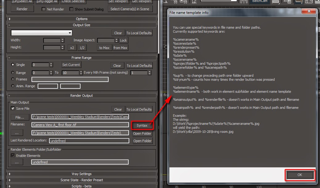


To do so, simply select the camera from the Camera Manager settings and click on the Copy button .
Next, select a new camera and click Paste.


Feel free to name the folders and/or sub-folders differently, if desired
Checkout below my other Courses with High Resolution Videos, 3d Project files and Textures to download.
 |
| Course 1: Exterior Daylight with V-Ray + 3ds Max + Photoshop |
Course 2: Exterior Night with V-Ray + 3ds Max + Photoshop |
| Course 4: Interior Daylight with V-Ray + 3ds Max + Photoshop |
 |
| Course 5: Interior Night with V-Ray + 3ds Max + Photoshop |
 |
| Course 6: Studio Lights with V-Ray + 3ds Max + Photoshop |
 |
| Course 7: Planning Applications for Verified Views |
 | |
| Course 8: 3d People + 3ds Max + VRay + Photoshop |
Also, please Join my Patreon page or Gumroad page to download Courses; Project files; Watch more Videos and receive Technical Support. Finally, check my New channels below:


3d Rendering: Is the process of converting the three dimensional (3D) data seen in a 3d scene into 2D image/s (rasterized).
The rasterization process include, the rendering parameters, the rendering engine, lights, 3d models, textures, shaders, and other effects.
3D renders can be a sequence of animated objects/effects/cameras, or a single frame with a still camera and object/s.
Some of the articles, Videos and Tutorials depicted here will take you through the process of rendering.
Photorealistic Rendering: Is the Process or Art of making a typical Computer Generated Image/render (CGI) look indistinguishable from a real photo.
To achieve this, users often need to possess the skills and the"eye" to appreciate good photography, cameras, composition, lighting, shaders, materials, 3d modelling, rendering and have some post-production skills.
Some of the articles, Videos and Tutorials depicted here will help you achieve truly photorealistic renderings.
Post-Production: Is the process of creating effects or/and results after (post) the main process.
This terminology can be used to describe the results (post-production) of main processes such as 3d renderings and/or filming a scene.
The post-production often occurs in applications such as Photoshop, After Effects, Nuke, etc.
Some of the articles, Videos and Tutorials depicted here will take you through the process.
Textures: Is a term often used to describe photographed 2d images to be later used in a toggle of a shader or procedural map.
Textures can be used in the Diffuse toggle, Reflect, Glossy effects, Bump, Displacement, etc.
Some of the articles, Videos and Tutorials depicted here will take you through the process of applying textures.
Materials: Is a term often used to describe maps, textures,procedural maps or shaders, depending on the context the term is being used.
Some of the articles, Videos and Tutorials depicted here will take you through the process of applying materials.
Procedural materials: Is a term often used to describe maps with editable/proprietary parameters/functions.
Some of the articles, Videos and Tutorials depicted here will take you through the process of applying procedural materials.
Shaders: Is a term often used to describe complex materials with functions and procedural maps created for a specific purpose.
Some of the articles, Videos and Tutorials depicted here will take you through the process of applying shaders.
Studio Lights: They are fundamental in the process of creating appealing images/renders.
Lighting determines not only the brightness and darkness, but also the tone, mood and the atmosphere of a scene.
Hence the importance to control and manipulate the lights accordingly, in order to fully capture the textures and the vibrancy of your objects.
By distributing the shadows and the highlights accurately, you can achieve truly appealing images/renders.
In addition, there is a huge online support for this software, and countless online sites with tips and tutorials.
Finally, there are readily available books, online/college courses, and its full documentation at Adobe.com
A 3d Visualiser works within the realm of 3d visualization, a sector of the Computer Graphics Industry (or CGI) that is primarily concerned with the visual presentation of design concepts and ideas. And a company within the 3d visualisation sector offers to its customers (among many things) 3d Visualization Services.
More tips and Tricks:
Post-production techniques
Tips & tricks for architectural Visualisation: Part 1
Essential tips & tricks for VRay & mental ray
Photorealistic Rendering
Creating Customised IES lights
Realistic materials
Creating a velvet/suede material
nice
ReplyDeleteNice Post.
ReplyDeleteThank you very much VR Real and Onsite3D. It's much appreciated!
ReplyDeletenice
ReplyDelete